


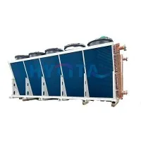
Finned Tube Heat Exchanger Selection Guide: Principles, Comparison, Parameters, Customization & Maintenance
Most finned tube exchangers that lose their duty within the first six months were not built badly. They were selected for the wrong working conditions: a gas temperature that only holds at startup, a dust load nobody measured, a cleaning method the maintenance team cannot actually perform. Everything looked reasonable on the quotation, and then the plant ran a little hotter and a little dirtier than the specification assumed.
What follows is the sequence we work through with buyers - what the exchanger does and where the surface goes, how it compares with shell-and-tube and plate units, which parameters fix the design, how custom builds handle dust, heat and corrosion, and what keeps the unit running after commissioning. Read it before you request drawings. The decisions that later turn into expensive mistakes are usually made in the first three sections.
1 What a finned tube heat exchanger is
Core Working Principle

Gas is the awkward side of gas-liquid heat transfer. Its coefficient is much lower than a liquid's, so a bare tube bank has to be enormous to reach a given duty. Fins attack exactly that imbalance: they add surface where surface is scarce, on the gas side, while the tube bore is left to the liquid or steam.
Heat travels from the gas, across the fin surface, through the tube wall, into the tube-side fluid. Nothing exotic in principle, but every design decision follows from it - how many fins, how far apart, in what material, and how the bundle will be cleaned.
A plain tube is roughly one radiator panel. Fins stack that panel many times over inside the same casing.
Core Structure & Main Fin Types
A bundle is base tubes, fins, and a frame or tube box. Three fin types cover most industrial duty:
Fin type Applicable temperature
|
Fin Type |
Applicable Temperature |
|
Extruded fin tube |
≤250℃ |
|
Inserted fin tube |
≤350℃ |
|
Welded fin tube |
≤500℃ |

Those ranges are a starting point, not the whole selection. A fin that survives 350℃ in clean gas can be the wrong choice at 250℃ in a chloride stream.
Main Application Industries
Chemical: process gas cooling and waste heat recovery, usually with corrosion and dust present
Power: boiler flue gas waste heat recovery and air-cooled systems, high temperature and dusty
Waste heat recovery: flue gas heat recycling and drying-system exchange, on working conditions that shift a lot
HVAC: air heating and fresh-air exchange in large buildings, low temperature and clean
2 Finned Tube Heat Exchanger vs Other Heat Exchangers
Against shell & tube
Shell-and-tube units remain the workhorse for liquid-liquid duty. The comparison only gets interesting on the gas side.

|
Comparison Item |
Finned Tube Heat Exchanger |
Shell & Tube Heat Exchanger |
|
Suitable medium |
Gas-liquid / gas-steam |
Liquid-liquid, high-pressure, heavily corrosive fluid |
|
Unit heat area cost |
Lower for gas side |
Higher for gas side |
|
Footprint |
Compact |
Large |
|
Maintenance difficulty |
Medium |
Medium-high |
|
Anti-dust blocking ability |
Good |
Poor |
On gas cooling and flue gas heat recovery, the finned unit wins on footprint and on the cost of surface. On pure liquid-liquid duty, at high pressure, or against strongly corrosive fluids, the shell-and-tube unit is usually the better buy.
Plate exchangers are the other common option at medium and low temperature, and the two types differ sharply in what they can tolerate.
Comparison with Plate Heat Exchanger
Plate units are compact and efficient. On clean, low-pressure liquid duty at moderate temperature there is little reason to look elsewhere. Dust and heat are where they stop:

|
Comparison Item |
Finned Tube Heat Exchanger |
Plate Heat Exchanger |
|
Medium requirement |
Tolerate dust and impurities |
Require clean fluid |
|
Anti-blocking performance |
Good |
Poor |
|
Max working temperature |
Up to 500℃+ |
Normally below 180℃ |
|
Max working pressure |
Up to 4.0MPa |
Low to medium pressure |
|
Volumetric heat efficiency |
Medium |
High |
Plate units want clean fluid, low pressure and moderate temperature. A dusty, hot, high-pressure gas stream is not their territory. The recurring mistake here is buying plate efficiency first and checking the dust load and temperature ceiling afterwards.
When Should You Choose Finned Tube Type?
Choose it when:
heat passes between gas and liquid, or gas and steam;
the gas side carries dust or impurities and needs some tolerance for blocking;
working temperature is 200℃ or above, or the system pressure is beyond what a plate unit can hold;
the gas-liquid exchanger has to fit into a small space.
Skip it when the duty is clean liquid-liquid at mild temperature and pressure. Plate or shell-and-tube will cost less and work better. Once the category is settled, the parameters in the next section decide whether the unit lasts
3 Key Selection Parameters for Finned Tube Heat Exchangers
Fin Tube Material Selection
Material choice starts with corrosion, moves to temperature, and only then goes to cost.

|
Material |
Adapted Medium & Temperature |
Core Feature |
|
Carbon steel fin tube |
Steam, thermal oil, dry non-corrosive flue gas |
Low cost, not corrosion-resistant |
|
Stainless steel fin tube |
Slightly corrosive flue gas, weak acid fluid |
Good temperature and corrosion resistance, higher cost |
|
Aluminum fin tube |
Low-temperature clean air, HVAC |
Excellent thermal conductivity, low cost, not for high temp or corrosion |
|
Copper fin tube |
Clean water, low-temperature heat exchange |
Best thermal conductivity, expensive, vulnerable to acid and alkali |
One pitfall worth repeating: flue gas that carries sulfur cannot use ordinary carbon steel. Low-temperature dew point corrosion gets the tubes from the outside, and it does not take long.
With material fixed, the fin type has to match the conditions, not just the temperature limit.
Fin type against operating conditions
The temperature range tells you what will survive. Matching the fin to the site tells you what will perform.
| Fin Type | Suitable Operating Conditions | Key Advantages | Not Recommended For |
|---|---|---|---|
| Extruded fin tube | Medium-temperature clean gas streams | High thermal performance at the fin-base interface | Dusty gas services |
| Inserted fin tube | Medium-to-high temperature environments with mechanical vibration | Low contact thermal resistance between fin and base tube | Strongly corrosive process streams |
| Welded fin tube | High-temperature, high-pressure and dust-laden gas | Robust mechanical integrity and metallurgical bonding | Clean gas applications where capital cost is tightly constrained |
Work through it in this order: operating temperature, gas-side cleanliness, vibration level, project budget. Boiler flue gas that is both hot and heavily dusted is the standard case for welded stainless fin tubes. Once the fin method is fixed, pitch and density decide how area, pressure drop and fouling tendency trade against each other.
Fin pitch and fin density
Pitch is where the design exposes its trade-off. Tight spacing buys area and duty, and charges for it in gas-side pressure loss and in ash bridging. Wider spacing buys cleanability and gives up capacity.
Practical ranges:
clean gas or HVAC air heating: 2-4 mm pitch, high fin density
moderately dusty flue gas: 4-8 mm pitch, medium fin density
heavy dust or coke carryover: 8-15 mm pitch, low fin density
On dusty duty, cleanability and maintenance access outrank peak efficiency, and the pressure drop has to stay inside what the upstream fan can deliver. Specifying densely packed fins without evaluating ash deposition is a common field error, and those units are often badly fouled within six months. Pitch is not the only geometry that matters: base tube outside diameter, wall thickness and pass arrangement set the pressure containment and the tube-side flow distribution.
4. Custom design for severe conditions
Anti-fouling and anti-clogging for high-dust flue gas
Custom anti-clog bundles are built around three measures.
Fin geometry: pitch widened from 8 mm to 20 mm, with straight wide-fin profiles that give particles less to catch on.
Cleaning provisions: dedicated ports for compressed-air soot blowing or acoustic cleaning, plus bottom ash hoppers for continuous particulate discharge.
Extractable bundle: the whole finned assembly pulls out of the casing for offline deep cleaning.
The configuration suits boiler flue gas, dryer exhaust and mine-process dust-laden gas. Field reference: on a steel plant flue gas stream at 10 g/m³ dust loading, a custom bundle at 12 mm pitch with integral blow ports extended the required cleaning interval by a factor of six.
Fouling is one severe-service problem. Heat and pressure add two more, aimed at structure and sealing.
High temperature and high pressure
Three upgrades carry most of that duty: thick-walled seamless base tubes that satisfy the pressure code, fully welded fins that resist interface delamination under thermal cycling and hold thermal contact, and pressure-rated tube boxes with flange connections. Expansion joints are fitted where differential expansion has to go somewhere.
The envelope reaches 600℃ and 4.0 MPa. A typical build is a thermal oil circuit at 350℃ and 2.5 MPa in heavy-wall carbon steel with welded fins.
Chemical and pickling duty, where the fluid is acidic or alkaline, will destroy standard grades quickly and needs its own mitigation.
Corrosion control for acidic and alkaline media
Tier it by severity.
Mild: 304 stainless for base tube and fins, the balance point between performance and capital cost.
Moderate: 316L or duplex stainless for chloride-bearing streams and weak acid environments.
Severe: high-alloy substrate, or base metal protected with PTFE or silicone coating.
Good material matching needs the full fluid picture: composition, solute concentration, operating temperature. Specifying 304 for a chloride-bearing stream is a design oversight that surfaces as pitting corrosion, and it surfaces quickly.
Retrofit projects and cramped plant layouts add one more constraint, the installation envelope, and that is settled by mechanical layout rather than metallurgy.
All of these packages are built for identifiable severe-service modes, and the final geometry moves with the boundary conditions. Send the process medium, temperature, pressure, dust loading and available footprint, and the GA drawing and quotation can be prepared against real numbers.
5. Maintenance and fault response
Scheduled ash and deposit removal
Two cleaning methods do most of the work. Light ash comes off online with low-pressure compressed air; keep the nozzle pressure under control or the fins deform permanently. Heavy ash and mineral scale need offline high-pressure water, then thorough drying, because water left under a deposit corrodes the tube.
Cleaning intervals run from 1 to 6 months, set by the site dust load. Rigid tools are out. Scraping bends the fins and damages the surface that does the heat transfer.
Skipped maintenance turns the faults below into routine events.
Fault Root cause Remedial action
Degraded heat transfer efficiency ash fouling, tube-side scaling, internal leakage soot cleaning, chemical cleaning, leak testing and repair welding
Fin blockage or mechanical collapse excessive dust accumulation, overpressure during soot blowing manual fin combing, bundle replacement, blow pressure re-calibration
Tube wall corrosion and leakage fluid corrosion, low-temperature acid dew point condensation upgrade the corrosion alloy, add insulation to suppress dew formation
Abnormal system pressure flow path blockage, valve malfunction, sizing mismatch debottleneck the piping, inspect isolation and control valves, re-validate the thermal and hydraulic design
If duty drops again soon after every cleaning, the selection was wrong and the maintenance was not. That is an engineering conversation, not a cleaning schedule.
6. Two field cases
Flue gas cooler for waste heat recovery
A chemical plant's boiler waste heat unit kept losing performance to ash fouling. The redesigned bundle uses 304 stainless welded fin tubes at 10 mm pitch, with soot blow ports and bottom ash hoppers. It handles 320℃ flue gas at 8 g/m³ dust loading with trace SO₂. After 12 months of continuous run time, measured thermal efficiency degradation stays within 5%, and the cleaning interval has moved from 1 month to 6.
High-pressure thermal oil air heater
This air heater for a drying system uses thick-wall carbon steel base tubes, welded fins, pressure-rated tube boxes and thermal expansion joints. It accepts 320℃ thermal oil at 2.0 MPa and supplies process air at 180℃, and has run leak-free for two years at stable heat output.
References
Reid, D. R., & Taborek, J. (1993). Selection Criteria for Plain and Segmented Finned Tubes for Heat Recovery Systems. ASME International Gas Turbine and Aeroengine Congress and Exposition.
Admiralty Industries. (2025). Fin and Tube Heat Exchangers: Types, Design and Best Uses. Practical industrial guide covering fin types, material mapping and fouling-aware sizing.
Laier Heater. How to Choose the Right Finned Tube Heat Exchanger? Summarizes the core design principle from Kakaç: match exchanger geometry to thermal duty while respecting pressure drop and fouling limits.
EZ Steel Industrial. What Causes Finned Tube Fouling? Prevention and Cleaning Strategies; Main Causes of Fin Tube Efficiency Degradation and Optimization Countermeasures. Field-oriented notes on fouling mechanisms, cleaning and coating options.
Trianon Echangeur. How can you prevent a heat exchanger from becoming clogged? Discussion of fin pitch and maintainability for particulate-laden gas flows.